Technical Description of the MassVentil System
Background
Effective management of epidemics that cause acute respiratory distress (ARDS) such as COVID-19, SARS, or MERS, can only be defeated with vast amount of medical devices and effective medical care. The treatment process of acute respiratory problems involves continuous patient ventilation. Current medical practice implements ventilation with dedicated respiratory devices. A pandemic outbreak poses many problems in terms of hardware (medical ventilators) quantity, capacity, manageability, and installation.
Concept
During mass respiration in our mass ventilator concept, patients are connected to a modular or monolithically designed centralized ventilator system. In our concept the system can be designed and installed in a pre-built or ad hoc manner (in medical / non-medical facilities such as wards, sports grounds, gyms, etc.). The mass ventilator system is designed for the combined management of inhalation and exhalation gases (production, temperature / humidity / pressure adjustment, filtration, etc.). During inhalation and exhalation, the air is filtered in both directions in one or more steps.
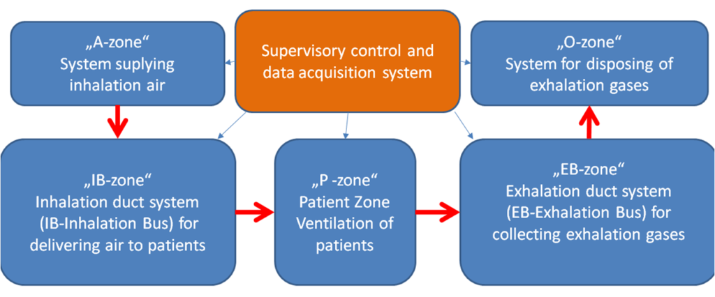
The management of respiratory gases (filtration, temperature control, humidity control, pressure control, safety control, etc.) is carried out in a distributed manner under centralized control in multiple locations within the mass ventilator system.
Our MassVentil concept is NOT based on a single patient ventilator concept. It is also NOT a co-ventilation based approach. Due to the modularity of the system, new patients can be integrated into the system up to the system’s maximum capacity. The maximum capacity of the system is mainly determined by the capacity of the motors used in the inhalation and exhalation system (important parameters: the amount and minimum pressure of the air supplied and size restrictions due to the environment).
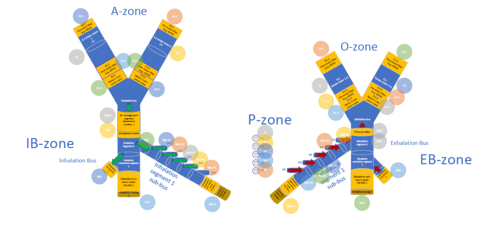
The inhalation air generator system (A-zone) can receive air from different sources. These can be buffer bottles (for both air and oxygen), hospital pre-installed aeration tubing, or dedicated ventilator or compressor based air supply systems. The combination or multiplication of different types of air-generating systems increases the capacity and robustness of the ventilator system (thereby increasing similar parameters of the entire mass-airway system). In the present example, a mass ventilator system comprising a fan motor air supply system is shown.
In this example, the flow of air for inhalation and exhalation is provided by separate ventilators (electrical). Power supply to the fans is provided with adequate redundancy and preferably uninterruptible power supply. The pressure ratios of inhalation and exhalation gases are defined and maintained so that no backflow or gas mixing occurs in the system.
On the inspiratory side (IB-zone), an excess pressure of at least 80 mbar is required. Both the inhalation air supply system and exhalation air dispensing system are redundant in order to remain operational in case of hardware problems and to be able to perform maintenance work (e.g. replacement of filters). A minimum of two fans per inhalation and exhalation site is required to achieve adequate redundancy.
Fans must be fitted with filter (s) to exclude contaminants and pathogens (e.g.: COVID-19 virus) of different sizes. It is also advisable to install filter (s) after the fan to prevent any contamination that may occur during replacement of the external filter (s) or engine operation. As the filters become dirty, their resistance increases, and the increased pressure difference must be monitored by a pressure gauge to avoid exceeding the performance of the aeration system (fan), in which case the operating point is shifted to an undesirable range. The heat generated by the continuous operation of the fan should be monitored continuously to avoid overheating.
Each fan is connected to the duct system via non-return valves (IB-zone and EB-zone). The duct system pressure can be set to the desired value by means of adjustable valves located at the end of the inhalation and exhalation ducts (the main ducts). The flow rate should be continuously measured in the main duct to ensure that it is sufficient for patients connected to the system. Parameters to be measured in the duct system are as follows:
- air temperature
- flow
- pressure loss on filters
- bus pressure
- air humidity
- concentration of gases in the air
- system integrity
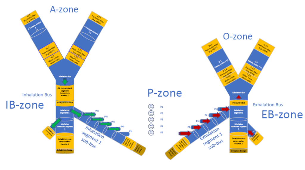
Both main ducts must be equipped with a mechanical pressure limiter (or even more) to prevent undesired operation. The inhalation duct may also optionally include an air management segment that measures and controls various important air parameters (temperature, heating-cooling, humidity, etc.). This segment is optional because parameters can be managed in other locations (e.g. in the patient P-zone). The inhalation and exhalation duct systems must be protected against static electricity with appropriate ESD protection by grounding the tubing.
Exhaled air is also transported via a centralized duct system, thus reducing the potential risk of infection for those working in the area. The exhaled air is contagious and for this reason the exhalation ducts must be appropriately marked and painted.
In the exhaled air transporting system, there is depression up to the pressure side of the fan, the pressure can be adjusted with a valve at the end of the exhalation duct and should be about -40 – -80 mbar lower than the outside air pressure. Due to the lower than atmospheric pressure, the pathogens cannot escape. The pressure side of the fan must be designed in such a way that the air can escape only after appropriate filtering.
The duct systems have to be connected to the devices of the patients via a separate shut-off device, so that new patients can be integrated into the system without any interruption in the whole system. A shut-off fitting must be provided at the end of the main ducts for the purpose of scalability.
Integration, Ventilation, and Removal of Individuals from the System
Patients receive air based on their personalized ventilation parameters (pressure, respiratory rate, volume, etc.). An intelligent metering-controlling-mixing-air management system near the patient is responsible for personalized patient ventilation. Due to the modularity of the system, new patients can be integrated into the system without having to stop ventilating already connected patients.
The ventilator system is divided into larger segments, which include closures (both in the exhalation and inhalation subsystems). Segment locks serve as gates which, when opened, can deliver air to another segment under specific pressure conditions.
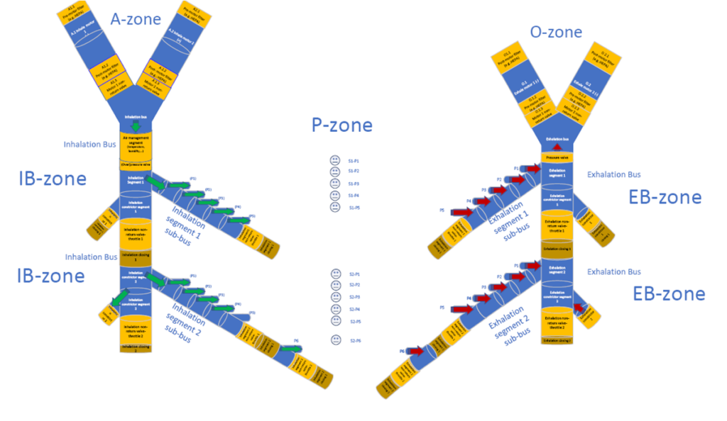
One or more patients may be connected in each segment at a time. Patients in one segment can be individually integrated into the system or removed from the system at any time independently of the other patients. Connection and disconnection of a given patient module is accomplished by patient level control. The patient is connected to a sub-duct of a particular segment via a three-passage control valve. The valve body is designed so, that by rotating the valve we start from maximum inflow and end at maximum outflow status. Thanks to this, the patient side pressure can be gently controlled. By varying the flow cross sections of the valve’s pressurized passage (connected to the inhalation duct segment) and the depressurised passage (connected to the exhalation duct segment), the desired pressure and flow rate are produced in the third passage leading to a patient tube or mask. The control of air pressure and flow can be achieved by active or passive control loops. Thanks to the model-based calibration, in addition to complex mechanisms, even a simpler (but efficient) control loop can be created and pressure and flow control can be achieved with a simple stepped motor position control.
In the P-zone, the system provides several options for adjusting the O2 concentration of each patient: oxygen delivery can be achieved by concentration-based or even time-based control. It is difficult to obtain relatively expensive and accurate O2 sensors for use in concentration-based control and to replace them continuously (periodically) in an epidemic situation. With time-based control, the accuracy is lower, but still suitable for operation. The constant amount of gas delivered per unit time by a mechanical O2 flow control valve is delivered to the patient by controlling the solenoid valve at suitable time periods. Thanks to the mechanical flow controller, the amount of O2 introduced does not depend on the difference in pressure in the O2 supply system and in the P-zone, it depends only on the time period of delivery. In flow control mode, a predetermined amount of ambient air is supplied so that the required O2 can be calculated accurately. In pressure control mode, depending on the patient’s condition and parameters (which may change over time), different amounts of ambient air can be injected, so that the required additional O2 concentration (the difference between two cycles) is calculated using the O2 quantity of the previous breathing cycle.
The temperature and humidity of the air supplied to the patient can be controlled both in IB-zone and P-zone. In the P-zone humidity and temperature control is easier, thus it is possible to set the desired values in the vicinity of the patient’s mouth by passive (e.g. HME – Heat and Moisture Exchangers) or active solutions (e.g. HME Booster).
Free Breathing Function
Due to the design of the system, the P-zone is not completely blocked from either the IB-zone or the EB-zone, allowing the patient to breathe freely. In addition the operation is synchronized with the patient’s respiratory cycle: if the patient is breathing at a different rate the system will still provide the required amount of air. The excess air that the patient produces or requests during inhalation or exhalation is transported by the sub-ducts.
By setting the inhalation pressure of the patient in the P-zone close to atmospheric pressure, the breathing of a patient with spontaneous breathing can be facilitated. Patient-induced pressure (during exhalation) and depression (during inhalation) can be reduced and increased to atmospheric pressure that allows the patient to exchange air freely and more easily.
Unified Monitoring of Patients
The mass ventilator system and all ventilated patients are monitored by a secure, SCADA like unified monitoring system. Measurement data, derivative values and statistics are transmitted to the local (or central) server(s) over a wireless network using an appropriately encrypted (authenticated) communication channel. Because mass ventilation is theoretically feasible for large number of patients over relatively large areas, it may be necessary to use active wireless devices to bridge distances. Wireless Access Points (APs) can be integrated into the system to extend the coverage of the communication network.
The monitoring system shows different parts of the ventilator system and only those monitored parameters which are authorised for the personnel accessing the data based on the authentication and security settings. The monitoring system provides data transmission between the personal ventilator modules and the software monitoring, as well as to HISs (Hospital Information System) and advanced epidemiological monitoring systems.
The main measuring points of the system are located as shown below: